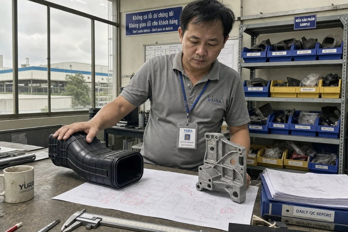
I review automotive component designs for blow molding every week, and many arrive half-suited to the process. Wrong process choice means tooling money wasted, launches delayed, and painful redesigns later.
An automotive component design is suitable for blow molding if it is fundamentally a hollow or double-walled part with drafted surfaces, generous radii, minimal undercuts, and tolerance requirements that accept moderate wall thickness variation. Solid, precision-detailed parts are usually better made by injection molding.
The good news is that suitability can be judged early, before any steel is cut. Below, I walk through the four questions our engineering team asks on every project.
How can I tell if my part's wall thickness is right for blow molding?
A duct project we managed through our Vietnam office taught me this lesson early: the CAD model showed uniform walls, but the first samples thinned badly at one deep corner.
Your wall thickness is right for blow molding if the nominal wall falls roughly between 1.5 mm and 4 mm, the blow ratio stays below about 3:1, and deep-draw zones can tolerate thinning of 30–50 percent from the nominal specified wall.
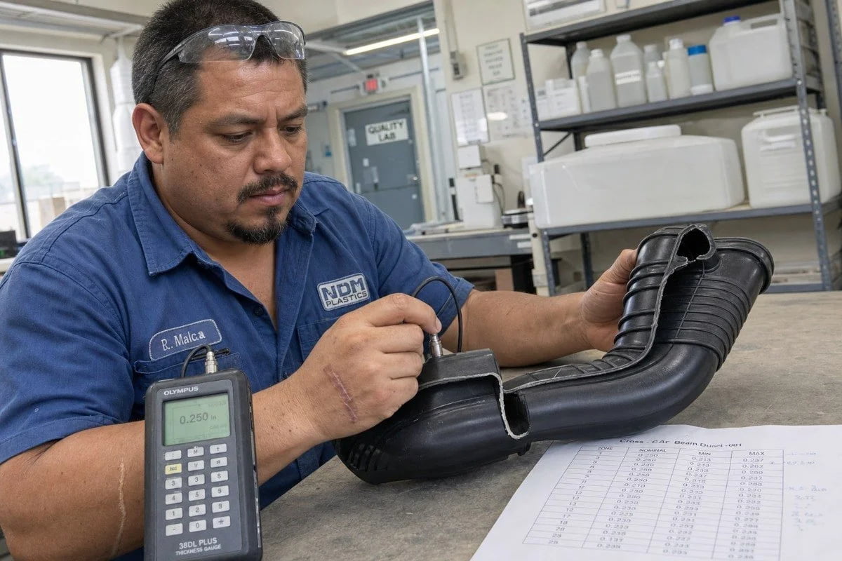
Épaisseur de paroi 1 uniformity is the single hardest thing to control in extrusion blow molding. Unlike injection molding, the material is not forced into a fixed cavity gap. Instead, a molten tube called a parison inflates against the mold surface. Areas that stretch more end up thinner. So your drawing should never assume the wall will be uniform automatically.
Check your blow ratio first
The blow ratio compares the part's maximum width to the parison diameter. When we quote a project, this is the first number our engineers calculate. A ratio above 3:1 usually signals excessive thinning in deep-draw areas, which creates weak spots under vibration or pressure load.
Use parison programming to fight thinning
Modern machines adjust the parison wall along its length before inflation. Parison programming lets a supplier push extra material into zones that will stretch the most. But programming has limits. It cannot fix a geometry that stretches five times more in one region than another.
| Design check | Safe zone | Risk zone |
|---|---|---|
| Nominal wall | 1.5–4 mm | Below 1 mm or above 6 mm |
| Rapport de soufflage | Under 3:1 | Over 3:1 |
| Corner thinning | Under 30% loss | Over 50% loss |
| Wall variation spec | ±25% or looser | Tighter than ±10% |
If your drawing demands injection-molding-grade thickness control, either loosen the spec or reconsider the process.
What design changes should I make to avoid warping in my automotive component?
One of our U.S. buyers once rejected a full container of air ducts because flanges bowed after cooling. The root cause was not the factory. It was the geometry.
To avoid warping, design smooth radii instead of sharp corners, keep section changes gradual, balance wall thickness across the part, place the parting line on a neutral plane, and account for material shrinkage rates in every critical dimension before tooling begins.
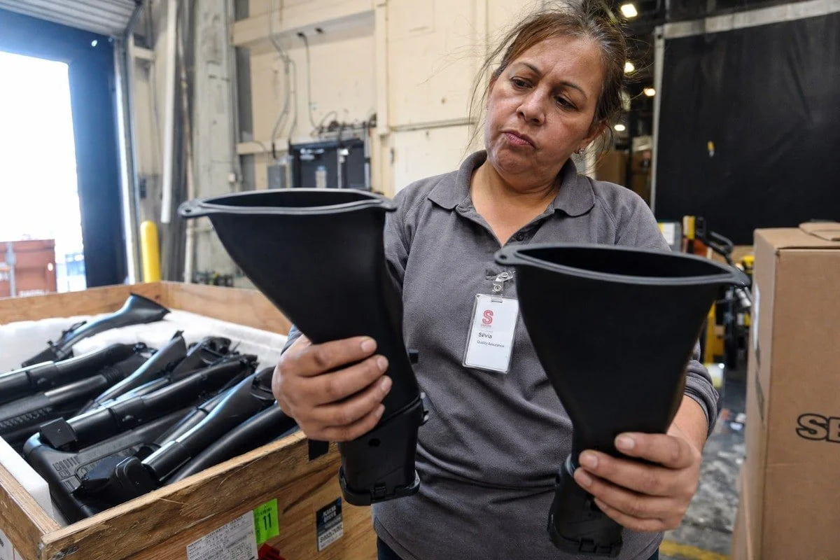
Warping happens when different regions of a part cool and shrink at different rates. Blow-molded parts are especially exposed because wall thickness already varies. Thick zones cool slowly and keep shrinking after thin zones have frozen. The result is internal stress that pulls the part out of shape.
Soften every transition
Sharp internal corners do two bad things at once. They concentrate stress, and they worsen thinning during inflation. A good blow-molded automotive design flows geometrically. We push clients toward radii of at least 3–5 mm on corners and gradual steps between sections. On durability parts facing thermal cycling and vibration, this matters even more, because toughness is often the reason you chose the process.
Respect shrinkage and the parting line
Material shrinkage rates differ sharply by resin. High-density polyethylene 2 can shrink 2 percent or more, while filled nylons shrink far less. Your tolerances must reflect the resin, not a generic plastic rule. Parting line placement matters too. A parting line running across a cosmetic face or a sealing surface invites flash, mismatch, and distortion complaints.
A practical anti-warp sequence
- Round all corners and blend all steps.
- Check for thick-to-thin jumps larger than 25 percent.
- Move the parting line off critical faces.
- Apply resin-specific shrink values to the tool design.
- Add gentle crowning to large flat panels, since flat walls almost always oil-can or bow.
Large flat surfaces are the most common warp trap we see on automotive trim and panel concepts. A slight curve hides distortion and stiffens the wall at zero cost.
Which materials should I choose to ensure my component performs well when blow molded?
Melt behavior, not just datasheet strength, drives this decision. During supplier audits across Vietnam and Taiwan, the first thing we verify is which resins a line actually runs well.
Choose resins with high melt strength, such as high-density polyethylene and polypropylene, for most automotive blow molding. Use glass-filled nylon for under-hood heat, TPV for flexible ducts, and multi-layer co-extrusion when barrier properties or recycled content are required.

Blow molding puts one unusual demand on a plastic: the molten parison must hang under its own weight without sagging before the mold closes. That property is called melt strength. Resins that flow beautifully in injection molding can fail completely here. This is why high-density polyethylene dominates tanks and reservoirs, and why polypropylene leads in air ducts.
Match the resin to the duty
| Matériau | Typical automotive use | Key strength | Watch out for |
|---|---|---|---|
| HDPE | Fluid reservoirs, washer tanks | Melt strength, chemical resistance | High shrinkage, low stiffness |
| PP | Air ducts, HVAC parts | Heat resistance, low cost | Cold-temperature brittleness |
| Glass-filled nylon | Under-hood air intake | Strength at high heat | Moisture uptake, tooling wear |
| TPV | Flexible ducts, bellows | Flexibility, fatigue life | Higher resin cost |
| EVA / NBR-PVC | Soft-touch and sealing parts | Softness, damping | Limited structural use |
Consider multi-layer co-extrusion
Multi-layer co-extrusion lets you bury a high-percentage recycled (PCR) layer 3 inside the wall while keeping virgin material on visible surfaces. Several of our European-bound projects now request this to meet circular-economy targets without hurting the exterior finish. It also enables barrier layers for fuel and coolant applications, including emerging EV battery cooling jackets where seamless complex hollow geometries eliminate leak paths.
Do I need to redesign my part's geometry to eliminate undercuts before blow molding?
The trade-off I weigh most often on quotes is this one: keep an undercut and pay for side actions, or redesign and keep tooling costs low.
You should eliminate or minimize undercuts before blow molding whenever possible. Small snap features can survive through collapsible tooling or flexible resins, but frequent deep undercuts, hidden hooks, and precise internal latches add cost, risk, and cycle time, and often justify redesign.
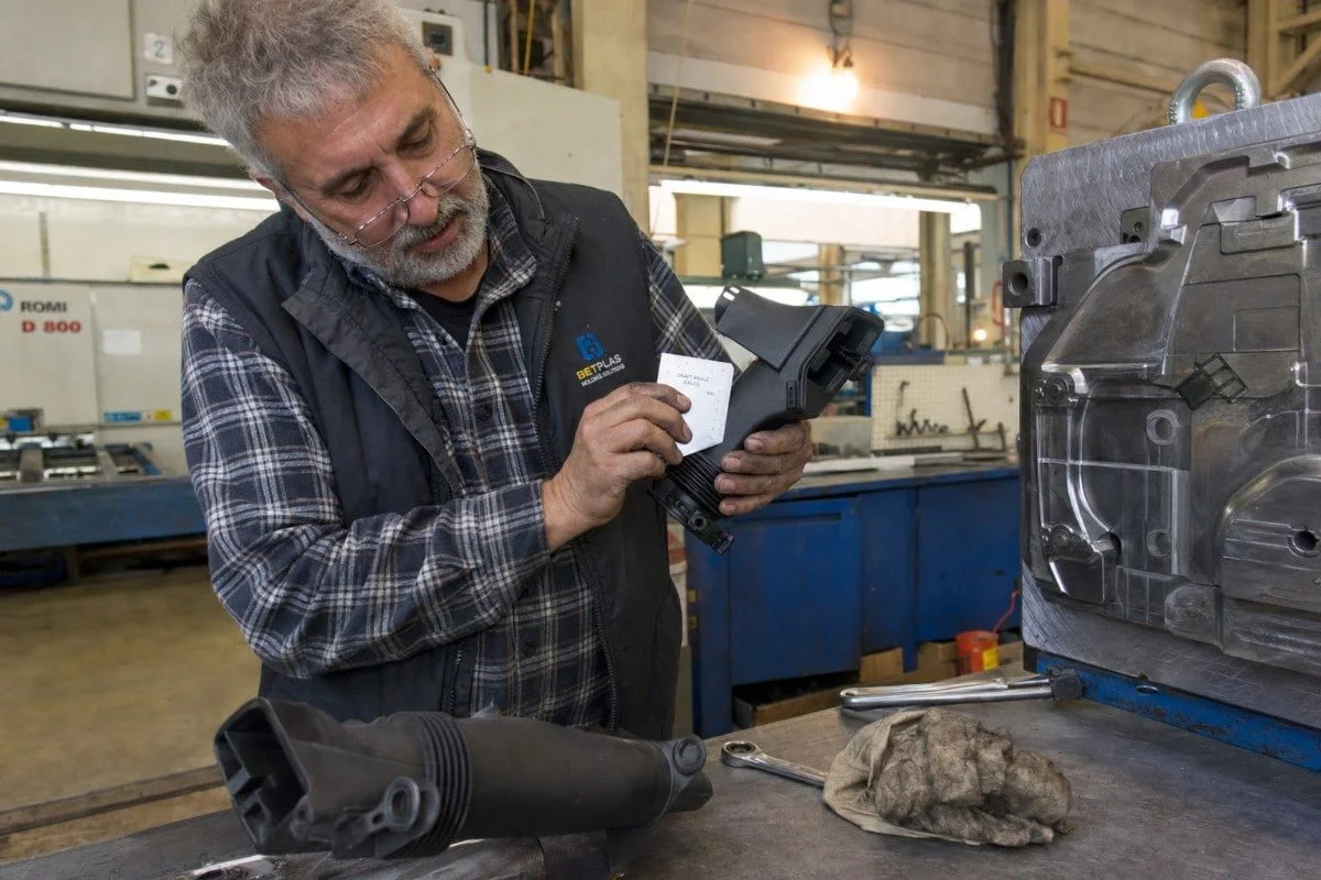
Blow molding is strongest when the part releases cleanly as the two mold halves open. Every feature that fights that motion adds mechanical complexity. Because the process runs at low internal pressure, tooling costs are already far lower than injection molds for large parts. Loading that advantage down with slides and lifters erases much of the savings.
Start with draft angle requirements
Draft angle requirements are non-negotiable. Vertical faces grip the mold, and insufficient draft 5 can damage both part and tool at ejection. We ask for at least 1 degree on smooth walls and 3 degrees or more on textured surfaces. Deep recesses and tall vertical walls need progressively more.
Grade your undercuts honestly
| Undercut type | Faisabilité | Typical solution |
|---|---|---|
| Shallow snap lip | Usually fine | Flexible resin strips over steel |
| Side port or window | Modéré | Post-mold machining or drilling |
| Deep reverse pocket | Difficile | Slide tooling, higher cost |
| Internal precision latch | Poor fit | Redesign or secondary assembled insert |
Use pinch-off design and tack-offs instead
Good pinch-off design matters wherever the mold halves seal the parison; a proper pinch-off keeps the weld line 6 at 60–80 percent of parent material strength. Internal tack-offs, where opposite walls fuse, add stiffness without side actions. On air-induction parts, tack-offs can even be shaped as Helmholtz resonators to quiet NVH frequencies. Often the smartest move is splitting the design: blow mold the hollow body, then attach precision features as injection-molded clips in secondary assembly.
Conclusion
Choosing the wrong process wastes tooling budgets and delays launches. Judge your part honestly: hollow, drafted, radiused, and tolerance-realistic means blow molding fits. We help clients verify exactly that.
Notes de bas de page
1. Authoritative Wikipedia section covering design considerations and wall thickness for blow molding. ↩︎
2. Authoritative Wikipedia entry for high-density polyethylene properties and technical specifications. ↩︎
3. Authoritative EPA resource providing data and definitions for recycled plastic materials. ↩︎
4. Scientific definition of melt strength and its critical role in the stability of the molten parison. ↩︎
5. Engineering principles regarding draft angles and the mechanical issues caused by insufficient draft during part ejection. ↩︎
6. Definition of weld lines in plastic manufacturing and their impact on the structural integrity of the final part. ↩︎



 English
  Español de México
  Deutsch
  Français
  Русский
  العربية
Laisser un commentaire
Votre adresse e-mail ne sera pas publiée. Les champs obligatoires sont marqués *