We see too many projects struggle because buyers rely solely on paper certificates rather than verifying the physical process. When we develop custom frames for US clients, we know that unchecked dimensional drift ruins assembly lines and kills profit margins.
To verify a supplier’s machining accuracy, request First Article Inspection (FAI) reports backed by CMM data and demand on-site audits of their fixture designs. You must also evaluate their post-weld stress relief procedures and calibration records for multi-axis CNC machinery to ensure consistent tolerance control.
Here is how you can systematically validate a manufacturer’s capabilities before signing a contract.
What specific machining and welding equipment ensures the tightest tolerances for my parts?
When we set up our production lines in Vietnam, we prioritized automated machinery because manual setups introduce human error that kills precision. automated machinery 1 Relying on basic welding tables guarantees inconsistency and costly rework for complex assemblies.
Look for suppliers utilizing 5-axis CNC machining centers for single-setup precision and robotic welding cells that offer high repeatability. Additionally, verify the presence of Coordinate Measuring Machines (CMM) and laser trackers, which are essential for validating tight tolerances on complex welded assemblies.

To truly understand if a supplier can meet your specifications, you must look beyond their marketing brochures and audit their equipment list. In precision manufacturing, the machine determines the baseline capability. If a shop relies heavily on manual milling machines and handheld welding torches for complex geometries, they will struggle to hold tolerances tighter than ±0.5mm over a production run.
The Necessity of 5-Axis CNC Machining
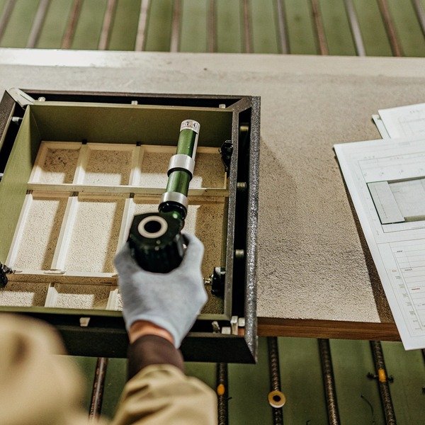
For welded frames, like the aluminum structure shown in the image above, machining often needs to happen after welding to ensure flat mounting surfaces. If a supplier uses a standard 3-axis machine, they may need to unclamp, rotate, and reclamp the part multiple times to reach all sides. Every time a part is moved, the reference point (datum) shifts slightly, introducing "stack-up error."
We use 5-axis CNC machines because they allow the cutting tool to approach the part from virtually any angle in a single setup. 5-axis CNC machines 2 This ensures that the geometric relationship between features—such as the parallelism between the front and back uprights—remains perfect.
Robotic Welding Cells
Manual welding varies by the operator's mood, fatigue level, and skill. In contrast, robotic welding cells control the torch angle, travel speed, and wire feed rate with mathematical precision. robotic welding cells 3 This control is critical for tolerance. Consistent travel speed means consistent heat input. Consistent heat input means predictable thermal expansion and contraction. thermal expansion and contraction 4 If the heat varies, the metal warps unpredictably, making it impossible to hold tight dimensions.
Advanced Inspection Hardware
You cannot manufacture what you cannot measure. A tape measure is insufficient for precision parts. You need to see a Coordinate Measuring Machine (CMM) or a portable Laser Tracker on the shop floor. These tools map the physical part against the 3D CAD model, identifying deviations as small as a few microns.
Equipment Capability Comparison
| Equipment Type | Typical Tolerance Range | Risk Level for Precision Parts |
|---|---|---|
| Manual Mill / Lathe | ± 0.1mm – 0.2mm | High: Dependent on operator skill; risk of human error. |
| 3-Axis CNC | ± 0.02mm – 0.05mm | Medium: Multiple setups required for complex parts may introduce cumulative error. |
| 5-Axis CNC | ± 0.005mm – 0.01mm | Low: Single setup ensures maximum relative accuracy between features. |
| Robotic Welding | ± 0.5mm (positional) | Low: Consistent heat input reduces unpredictable warping. |
| Manual Welding | ± 1.0mm – 3.0mm | High: Variable heat input causes inconsistent distortion. |
How can I evaluate a manufacturer's quality control process to guarantee machining precision?
Our engineering team spends weeks refining QC charts for new export projects because we know that catching defects at the end is too late. Without real-time process monitoring, defects hide until final assembly at your warehouse.
Evaluate quality control by auditing their Statistical Process Control (SPC) data and in-process inspection points. A robust process must include mandatory hold points for dimensional checks after tack welding and post-machining verification using calibrated gauges to catch drift early.

Quality control is often misunderstood as a "final check" before shipping. However, for precision welding parts, checking the part only at the end is a recipe for disaster. If a weld frame is warped, machining it flat might make the wall thickness too thin, compromising structural integrity. Therefore, you must evaluate the supplier's process controls, not just their final inspection room.
Moving Beyond "Pass/Fail"
When we audit suppliers or manage our own lines, we look for look for Statistical Process Control 5 Statistical Process Control (SPC). Contrôle Statistique des Processus 6 This involves measuring key features on every 5th or 10th part and plotting the data on a graph. If the dimensions are slowly drifting toward the upper tolerance limit—perhaps because a cutting tool is wearing out—the operator can stop and adjust the machine before the parts become bad. If your supplier cannot show you these control charts, they are essentially guessing.
Mandatory Hold Points
A "Hold Point" is a stage in production where work must stop until a check is performed. For precision welding, we recommend the following critical hold points:
- Material Verification: Checking raw tubing dimensions before cutting.
- Tack Weld Inspection: Verifying alignment before the full weld is applied.
- Post-Weld / Pre-Machine: Checking if the frame has distorted beyond the machining allowance.
- Final Inspection: Full dimensional report.
Calibration is Non-Negotiable
We once encountered a supplier whose CMM was giving perfect results, but the parts didn't fit. It turned out their machine hadn't been calibrated in three years. You must ask to see the current calibration certificates for their measuring equipment. These certificates should be traceable to national standards (like NIST or ISO). If the "ruler" they are using is wrong, every part they ship will be wrong.
Key Quality Documents to Request
| Document Name | Objectif | Que rechercher |
|---|---|---|
| Control Plan | Outlines the entire QC roadmap. | Does it list specific tools (e.g., "Digital Caliper") for every check? |
| FMEA (Failure Mode Effects Analysis) | Predicts what could go wrong. | Do they have a plan for "Thermal Distortion" or "Fixture Wear"? |
| Calibration Log | Proves gauge accuracy. | Are dates current? Is there a stamp from an accredited lab? |
| Non-Conformance Report (NCR) | Records past mistakes. | A blank NCR log is suspicious. Look for how they fixed problems. |
What should I look for in a supplier's fixture design to prevent welding distortion?
We often redesign client fixtures because standard clamps allow too much thermal movement during the heating cycle. Poor tooling creates warped parts that no amount of subsequent machining can fix, leading to massive scrap rates.
Effective fixture design must incorporate robust clamping to resist thermal expansion and dedicated heat sinks to manage energy input. Verify that the supplier uses modular, heavy-duty fixtures with precise locating pins that maintain alignment throughout the entire welding and cooling cycle.

In precision welding, the fixture (jig) is just as important as the welding machine itself. When metal is melted, it expands; when it cools, it contracts and pulls. Without a professionally designed fixture, a rectangular frame will turn into a parallelogram or a twisted shape resembling a potato chip.
Robust Clamping vs. Over-Constraint
There is a fine line in fixture design. The clamps must be strong enough to hold the parts in place against the massive forces of cooling metal. However, they must also be placed correctly to avoid "locking in" stress that will cause the part to spring back the moment it is removed from the fixture.
When we evaluate a fixture design, we look for:
- Toggle Clamps: Quick-release clamps that apply high pressure (often 500lbs+).
- 3-2-1 Location Principle: A proper engineering method to lock a part in space using 3 points for the plane, 2 for the line, and 1 for the point.
- Poka-Yoke (Mistake Proofing): Pins or blocks that make it physically impossible to load the part backwards.
Heat Management Strategies
Good fixtures act as heat sinks. We often use copper backing bars in our fixtures. Copper absorbs heat much faster than steel or aluminum. By placing copper blocks behind the weld joint, we pull the heat away from the rest of the frame. This reduces the heat-affected zone (HAZ) and significantly lowers distortion. If a supplier is using simple steel blocks or wood (yes, we have seen this), they are not controlling the thermal cycle.
Pre-Cambering (Pre-Setting)
For long beams or frames, experienced welding engineers use "pre-cambering." If they know the weld will pull the beam up by 2mm, they design the fixture to bend the beam down by 2mm before welding. After welding, the forces cancel out, and the part ends up straight. Ask your potential supplier if they use pre-setting techniques. Their answer will instantly tell you if they are true experts or just basic assemblers.
Fixture Design Checklist
| Caractéristique | Function | Why it Matters for You |
|---|---|---|
| Copper Backing | Thermal Management | Rapidly dissipates heat to prevent warping. |
| Hydraulic Clamping | Consistent Pressure | Removes operator variability in tightening clamps. |
| Hardened Locator Pins | Wear Resistance | Soft pins wear out after 100 parts, causing drift. Hardened pins last. |
| Relief Cuts | Clearance | Ensures the weld bead doesn't fuse the part to the fixture itself. |
How do I use First Article Inspection data to verify a supplier's accuracy claims?
Our US clients demand rigorous data before authorizing mass production, and we encourage this scrutiny. Accepting a sample without a full dimensional map invites disaster during the first volume run, as a single lucky part proves nothing.
Use First Article Inspection (FAI) data to compare the physical part dimensions against the GD&T requirements in your technical drawings. Detailed FAI reports should highlight pass/fail criteria for every feature, identifying potential trend deviations before full-scale manufacturing begins.

The First Article Inspection (FAI) is the bridge between a prototype and mass production. First Article Inspection 7 It is not just a "golden sample" to look at; it is a data package. Standard practice often follows the AS9102 format 8 AS9102 format (from aerospace), which requires every single dimension, note, and callout on the drawing to be numbered (ballooned) and measured.
The "Golden Sample" Trap
A common trick in the industry is to hand-work a single sample until it is perfect and ship it to the client. The client approves it, but the factory cannot replicate it on the production line. To avoid this, you must demand that the FAI report includes the method of measurement. Did they use a CMM (good) or a tape measure (bad for precision)? Furthermore, ask for a capability study (CpK) on critical dimensions if they produced a small pilot run.
Interpreting GD&T in the Report
Your drawing likely has Geometric Dimensioning and Tolerancing 9 Geometric Dimensioning and Tolerancing (GD&T) symbols, like Flatness, Perpendicularity, or Position. Geometric Dimensioning and Tolerancing 10
- Flatness: Essential for mounting frames. If the frame rocks on the table, it fails.
- Position: Critical for bolt holes.
The FAI report must show the actual numbers. If the tolerance is ±0.1mm, and the result is +0.099mm, the part "Passes," but it is statistically dangerous. It is on the edge of failure. We look for these marginal passes as red flags. They indicate that the process is not centered and will likely produce scrap in the future.
Analyzing Trends
When reviewing the data, don't just look for "Pass." Look at the variance.
- Target: 100.00mm
- Sample 1: 100.02mm
- Sample 2: 100.03mm
- Sample 3: 100.04mm
Even if the tolerance is ±0.1mm, this rising trend indicates tool wear or thermal buildup in the fixture. A good supplier will spot this and adjust. A bad supplier will ignore it until Sample 9 fails.
What to Demand in an FAI Package
- Ballooned Drawing: A copy of your PDF with every requirement numbered.
- Dimensional Report: A spreadsheet matching the numbers, showing Nominal, Tolerance, Actual, and Deviation.
- Material Certs (MTRs): Proof that the aluminum or steel is the correct grade.
- Finish Certs: Thickness reports for anodizing or powder coating.
- Photos: Pictures of the part on the CMM or in the gauge.
Conclusion
Verifying a supplier for precision welding requires looking deeper than the finished surface. You must audit their equipment for automation, check their fixtures for thermal management, and analyze their data for process stability. Only then can you trust the part will fit.
Notes de bas de page
1. General background on the role of automation in reducing human error in manufacturing. ↩︎
2. Technical guide on the advantages of 5-axis machining for complex parts. ↩︎
3. Industry standards for the qualification of robotic welding personnel and systems. ↩︎
4. Educational resource explaining the physical principles of thermal expansion in matter. ↩︎
5. Authoritative NIST handbook defining the Statistical Process Control methodology. ↩︎
6. International standard for statistical methods in process management and control. ↩︎
7. Official US government procurement clause defining First Article Inspection requirements. ↩︎
8. Official SAE standard page for the Aerospace First Article Inspection requirements. ↩︎
9. Official ASME Y14.5 standard page governing GD&T definitions. ↩︎
10. Comprehensive guide to GD&T symbols and engineering tolerance standards. ↩︎